What Is PBR — and what is it good for?
PBR (Physically Based Rendering) is today’s global standard for digital materials — used in architecture, 3D design, gaming, VR and AR.
Properly digitized material iIt’s not just one photo of the material but a set of ideally seamless hi-res bitmaps – pictures (or textures) – each describing the surface in a certain way to the 3D software they are being used in. One is saying what the precise color is, another one tells the software about its structure, another describes the glosiness, transparency, imperfections and so on.


✍️ Key takeaways
📌 Why PBR standard matters and how it's used
📌 PBR maps and what each does
Why PBR Materials Matter
In architecture, design, and product visualization, materials are not just decorative surfaces. They are often the difference between an image that simply looks good and a visual decision that can be trusted. Architects, designers, and 3D artists need materials that react correctly to light, scale properly, show realistic surface structure, and behave consistently across different software, renderers, and real-time engines.
This is exactly where PBR materials become essential. A properly prepared physically based material does more than show the color of a product. It describes how the surface reflects light, how rough or glossy it is, how deep its structure appears, and how it behaves under different lighting conditions.
For Architects and designer
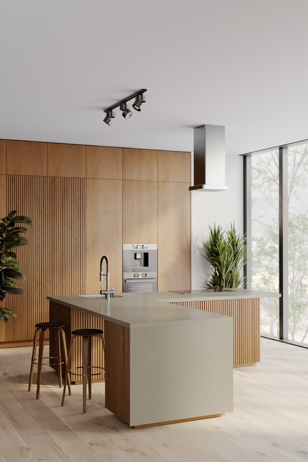
For architects and designers, this means better visual communication and fewer compromises. Instead of using generic textures that only resemble a real product, they can work with digital twins of actual materials from real manufacturers. This makes visualizations more reliable, because the product selected during the design process can also be specified and purchased in the real world.
Reawote is built around this idea: helping users choose the right 3D asset, create convincing visualizations for their clients, and connect the digital design process with real-world products. The platform focuses on PBR textures and 3D models from real manufacturers worldwide, not just anonymous or artificially created materials.
For manufacturers of surfaces
For manufacturers, high-quality PBR materials are becoming an important part of the product ecosystem. Architects, designers, and visualization artists increasingly make decisions inside digital environments, long before a physical sample is ordered or a showroom is visited. If a product is not available in a professional digital format, it can easily be left out of the design process.
By creating accurate digital twins of their surfaces, materials, or products, manufacturers make it easier for professionals to discover, test, present, and specify them in real projects. Reawote describes this directly as a way for manufacturers to distribute their products to thousands of potential customers worldwide through the visualizations of architects and designers.
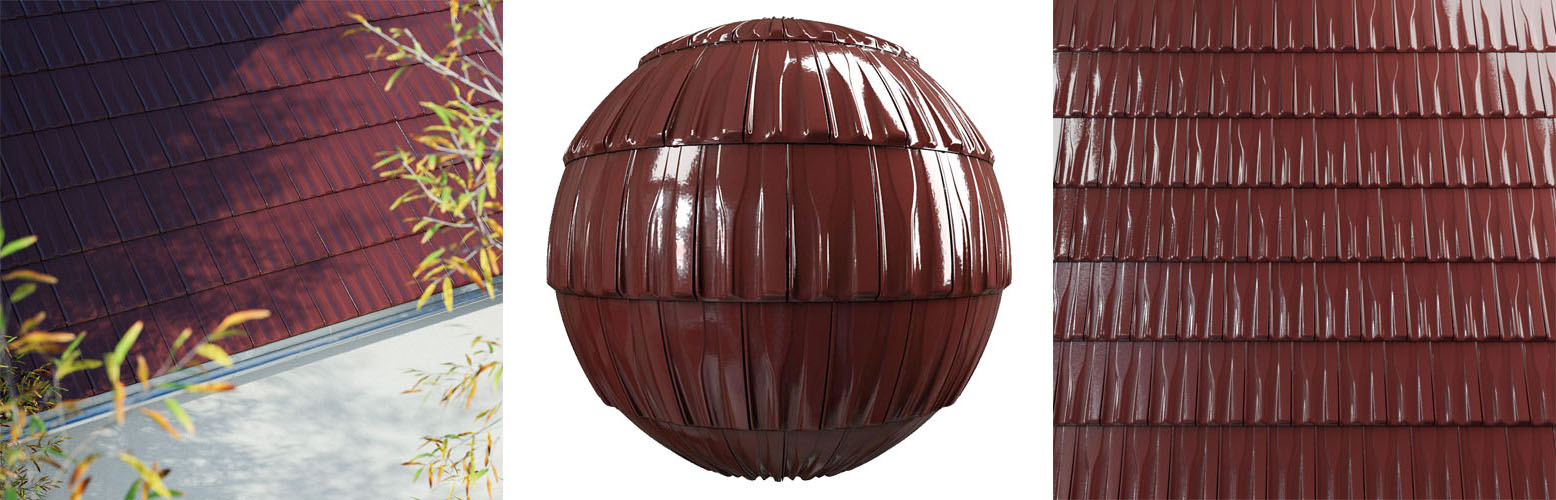
For manufacturers, the value is practical. One high-quality digitization process can create assets for architectural visualization, product presentations, online configurators, VR, AR, marketing images, animations, and custom production pipelines.
Reawote can support you
Reawote supports this through material scanning, 3D modeling, and high-end visualization services. The outputs are designed for digital twins, marketing, 3D visualizations, online configurators, and other digital platforms. With high-resolution PBR materials up to 16K and seamless, tileable textures, manufacturers get assets ready for professional visualization workflows.
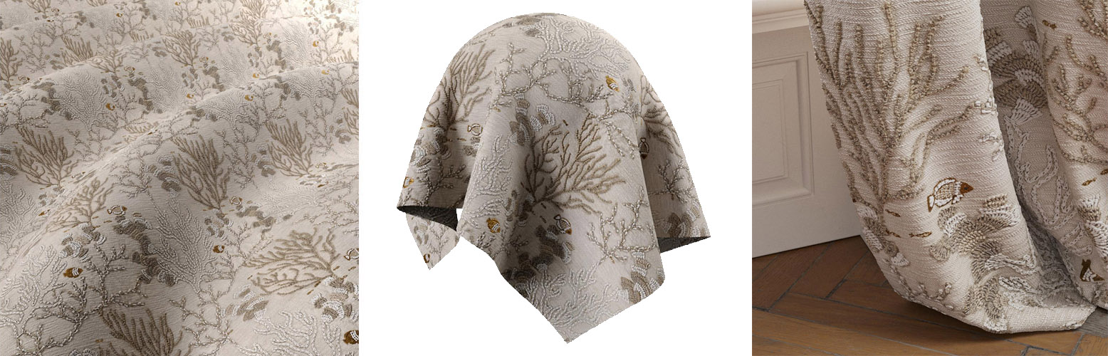
What does a PBR material include?
Simply put, a PBR material is a set of bitmaps. Producing these maps can be complex, but using a well-prepared PBR material is simple.
Do not let the list of maps below scare you. At first glance, PBR materials can look like a technical language made for render engines, but most of the complexity stays behind the scenes. When a material is accurately digitized and properly prepared, users can load it, adjust it if needed, and achieve consistent, realistic results across modern 3D applications, renderers, and real-time engines.
With Reawote digitization, materials are prepared as high-end, production-ready assets for architecture, product visualization, real-time environments, and custom pipelines. Our plugins for major 3D applications make the workflow even easier, allowing users to load and set up materials from our library with a single click.
Not every material requires all maps. Below are the maps we use for digitizing real-world materials, what they describe, and how they work.
Standard maps
Color (Diffuse)
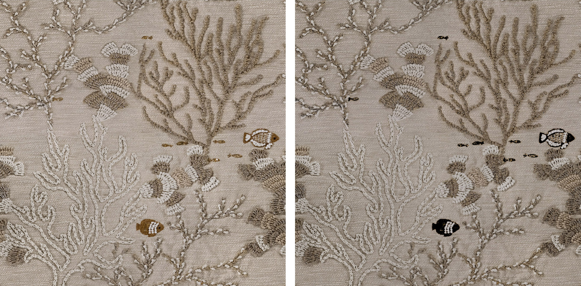
The Color map, often referred to as Diffuse or Base Color, defines the true visible color of a material without baked lighting, shadows, reflections, or ambient occlusion. In a physically based workflow, this map should describe only the intrinsic surface color. The renderer then calculates illumination, reflection, and shading based on the scene lighting, rather than relying on painted-in effects.
For dielectrics such as wood, stone, plaster, fabric, or plastic, the Color map represents the main reflected color of the surface. For metals, the color contributes directly to the tinted specular reflection instead of behaving like a traditional diffuse layer.
As a visual color texture, this map is normally interpreted in sRGB or gamma-encoded color space. This differs from data maps such as roughness, metallic, height, or normal maps, which should remain linear.
Normal map (16bit and 8bit)
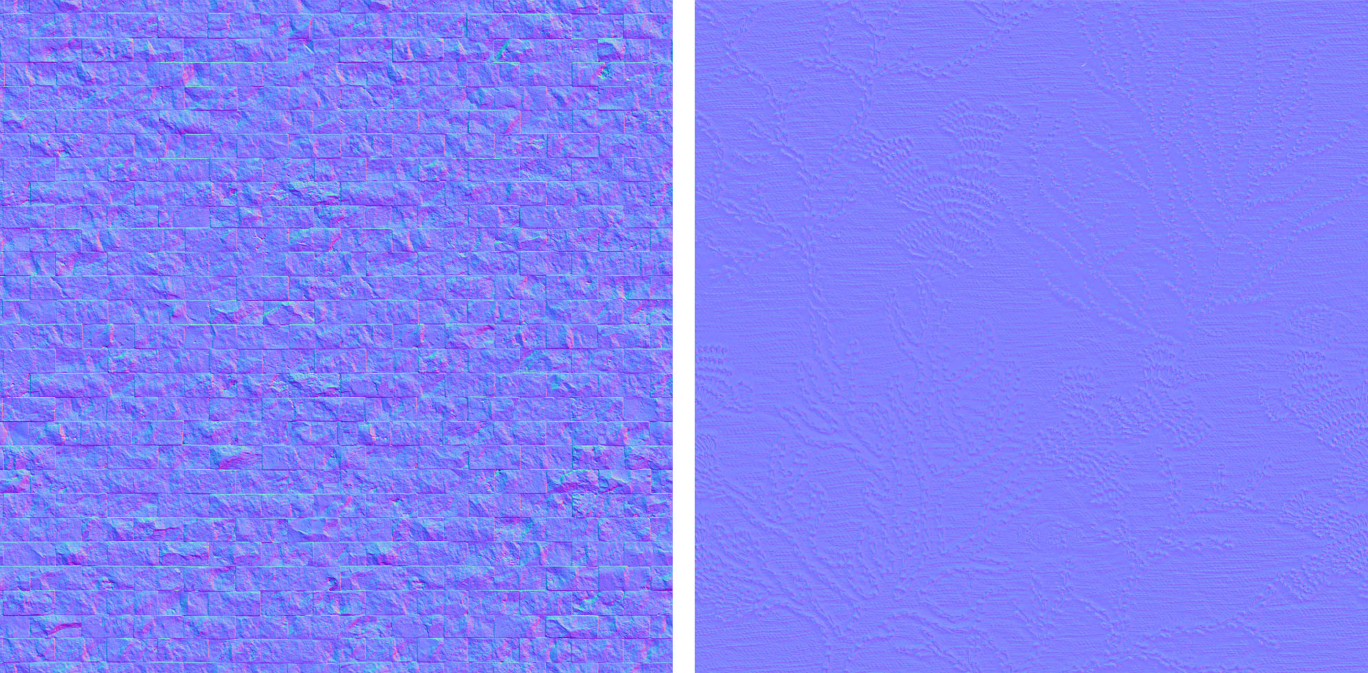
The Normal map describes high-frequency changes in surface direction without modifying the actual mesh silhouette. Instead of storing height, it stores encoded normal vectors that tell the shader how light should react to fine bumps, pores, scratches, fabric weave, chiseled stone, brushed grain, and other microstructure.
This makes the Normal map one of the most efficient ways to add realism. It creates a detailed lighting response at render time without requiring dense geometry.
Unlike ordinary grayscale or color textures, normal maps cannot be freely rotated, flipped, or edited as simple images without recalculating their vector data. Incorrectly changing their orientation can break the lighting direction and produce inverted or unrealistic shading.
Normal maps also use different tangent-space conventions, most commonly DirectX and OpenGL. These mainly differ in the orientation of the green channel. Using the wrong convention can make surface details appear inverted, so the normal map format should always match the target renderer or engine.
8-bit normal maps are widely used for real-time assets and game engines. 16-bit normal maps provide smoother gradients and reduce banding, especially on subtle scanned surfaces, large displacements converted to normals, or close-up architectural visualization assets.
Normal maps are technical data maps and should be treated as linear, not color-corrected images.
Height (Displacement) map (16bit and 8bit)
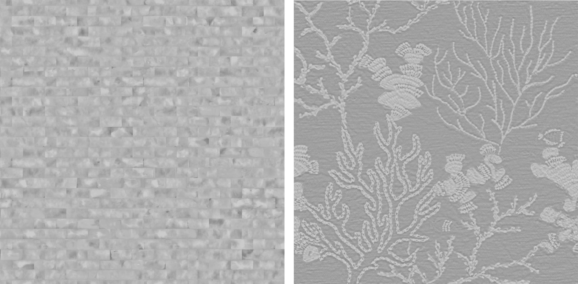
The Height map stores scalar depth information, usually as grayscale values where darker pixels represent lower areas and brighter pixels represent raised areas. Unlike a Normal map, which only changes how light reacts to the surface, a Height or Displacement map can be used to physically move geometry, generate parallax effects, or drive tessellation and micropolygon displacement in offline and real-time renderers.
It is essential for materials where real relief matters, such as structured concrete, stone walls, tiles, gravel, or bricks.
8-bit height maps are sufficient for broad or low-detail effects, but 16-bit height maps preserve much finer depth transitions. They are strongly preferred for production displacement because they reduce stepping, banding, and visible terrace artifacts.
Like roughness, metallic, normal, and ambient occlusion maps, height is a linear data map, not a photographic color texture.
Roughness and Glossiness map
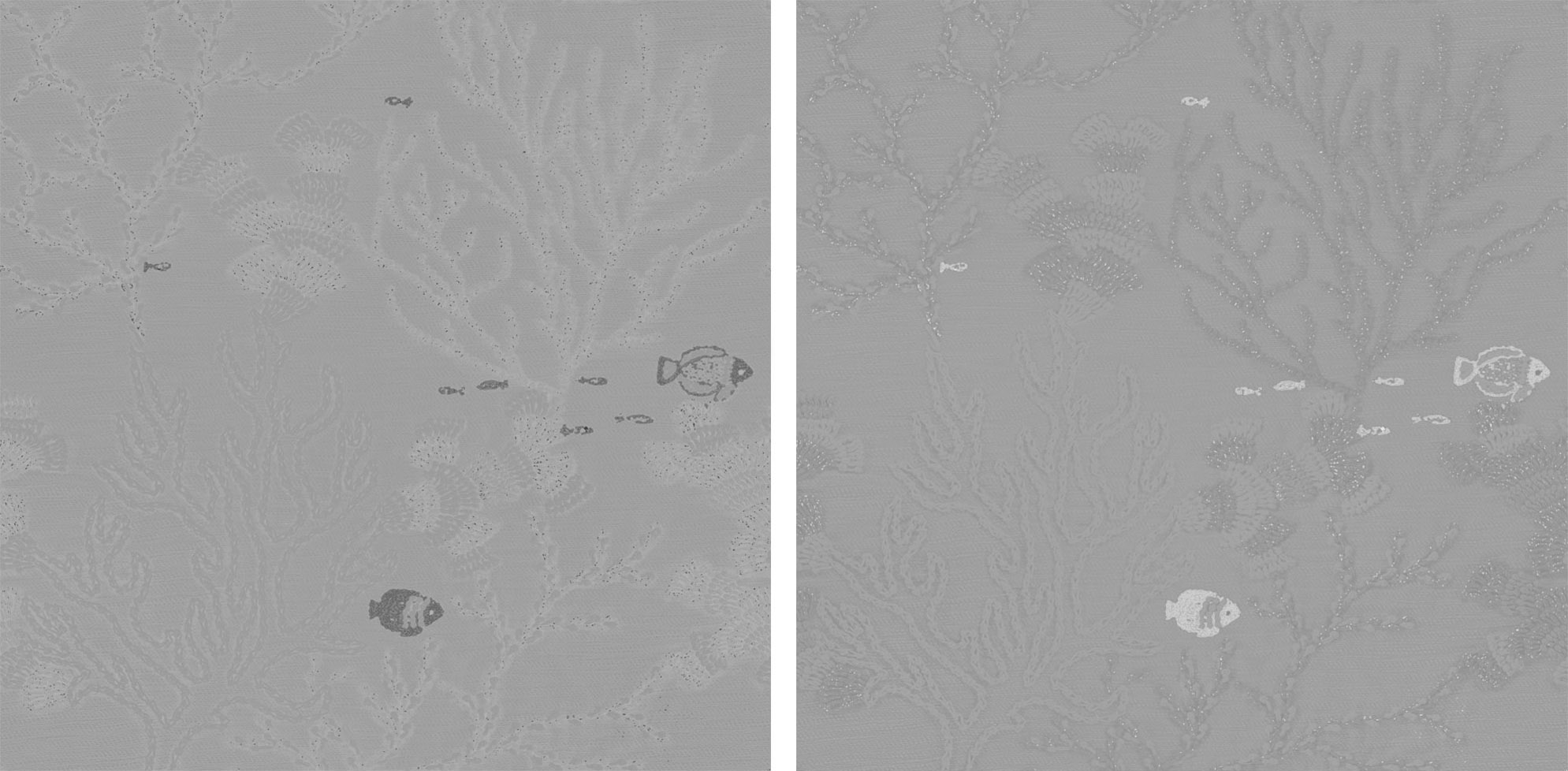
The Roughness map controls how microscopically smooth or irregular a surface is, directly affecting the sharpness and spread of reflections. Low roughness values create clear, mirror-like reflections, while high roughness values scatter reflected light into broader, softer highlights.
Glossiness describes the same idea from the opposite direction. High glossiness means a smooth surface with sharp reflections, while low glossiness corresponds to a matte, rough surface. Both maps describe the same physical property and are used in different PBR workflows, especially metal/roughness and specular/glossiness.
Accurate roughness or glossiness variation is one of the strongest contributors to believable materials. Real surfaces are rarely uniform: polished edges, worn paths, dust, oil, fingerprints, scratches, and weathering all change how reflections behave.
Roughness and glossiness maps are technical linear data maps and should not be gamma corrected.
Ambient occlusion map

The Ambient Occlusion map stores localized self-shadowing information, usually in cavities, cracks, seams, pores, overlaps, and contact areas where indirect ambient light would naturally be reduced. It should not replace physically calculated lighting, but it is useful for reinforcing small-scale depth and grounding fine material detail, especially in real-time rendering where full global illumination may be limited.
In practice, AO helps prevent materials from looking flat by adding subtle darkening to crevices such as wood grain, stone fissures, fabric folds, tile gaps, and sculpted ornament.
A well-authored AO map should remain controlled and physically plausible. It should enhance occluded areas without baking strong directional shadows or lighting into the base color.
Ambient occlusion is a linear data map.
Metallic map
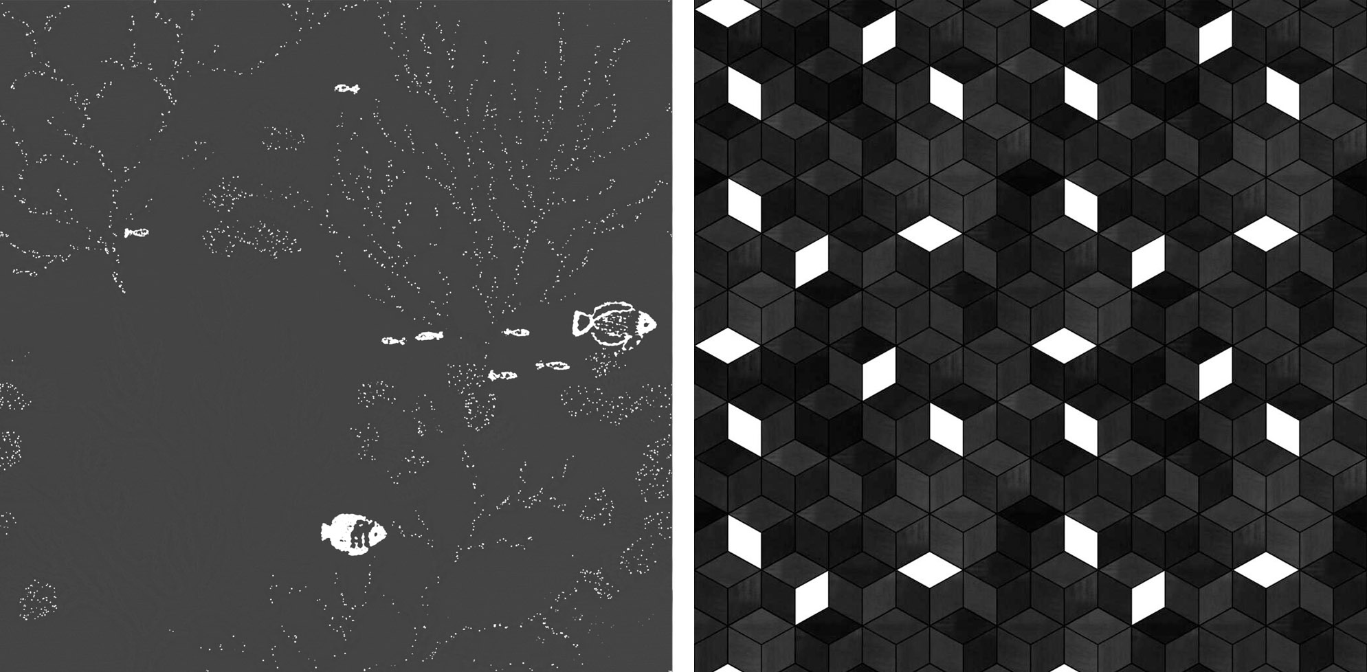
The Metallic map defines whether each part of a material behaves as a metal or a dielectric. It is a grayscale data map where black represents non-metallic materials such as stone, wood, plastic, ceramic, fabric, or paint, and white represents conductive metals such as iron, copper, brass, aluminium, or steel.
Metallic values control how the shader separates diffuse reflection from specular reflection. Dielectrics retain a diffuse base color with relatively neutral specular highlights, while metals have little to no diffuse component and derive their reflected color from the base color itself.
In production assets, the Metallic map is usually mostly binary. Intermediate values are used only for transitions, dirt, oxidation, worn paint, mixed materials, or scanned surfaces where metal and non-metal areas blend at the texel level.
Metallic maps are linear data maps.
Specular map
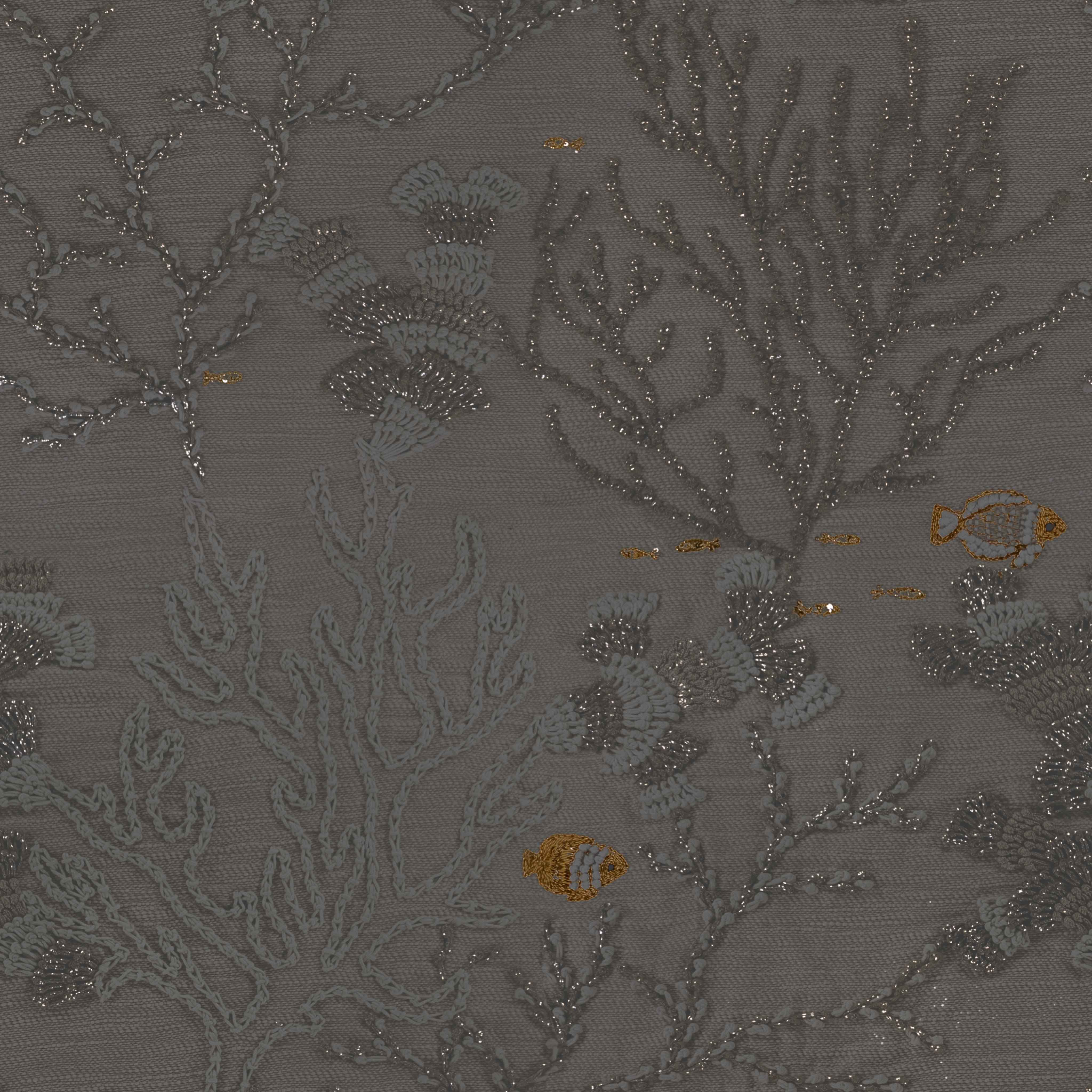
The Specular map defines the color and intensity of specular reflection in a specular/glossiness PBR workflow. Unlike the metallic workflow, where metalness determines whether the base color contributes to diffuse or metallic reflection, the specular workflow allows the reflection color to be authored directly.
This makes it useful for pipelines that require precise control over dielectric reflectance, tinted reflections, layered materials, gemstones, coated surfaces, or metals with a colored specular response.
For most non-metallic materials, the specular color should remain subtle and close to neutral, while metals can use stronger and more saturated specular values.
The Specular map should be treated as a technical reflectance input, not as a decorative color layer, and its interpretation depends on the target renderer or engine.
Opacity map
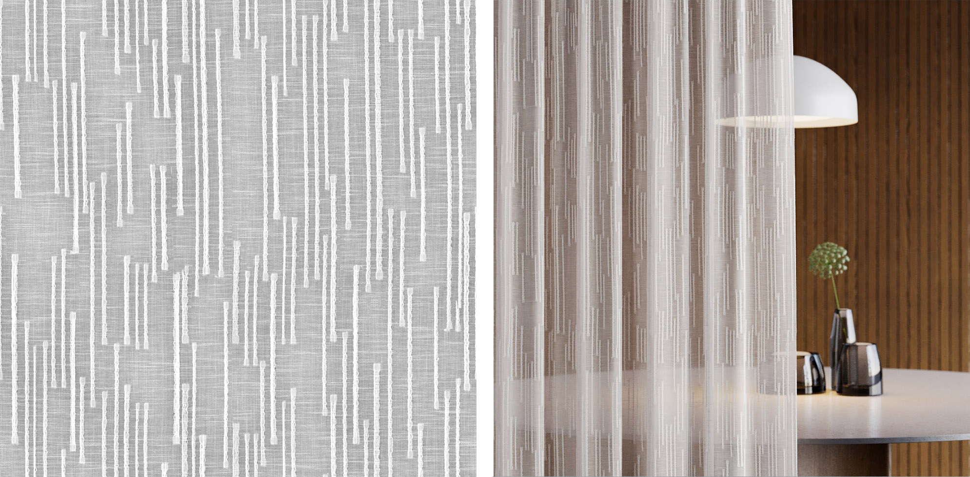
The Opacity map controls where a material is visible, partially transparent, or fully cut out. It is commonly used for leaves, decals, fences, grilles, lace, torn fabric, labels, perforated surfaces, and assets where modeling every opening would be inefficient.
Depending on the shader and rendering mode, opacity can work either as a binary alpha mask for sharp cutouts or as continuous transparency for glass-like and semi-transparent effects.
In PBR production, opacity should be used deliberately because it affects sorting, shadows, refraction, performance, and how the asset interacts with lighting. For clean real-time assets, an opacity mask is often preferred for hard-edged materials such as foliage cards or mesh decals. Physically transmissive materials, such as glass, usually require a dedicated transmission setup rather than simple alpha blending.
ID map
The ID map is a technical utility map used to separate different material zones, surface regions, or logical parts of an asset. It usually stores flat colors or indexed values rather than physical shading information, making it useful for masking, procedural texturing, color variation, material blending, dirt placement, edge wear, decals, and selective editing.
In Reawote materials, ID maps are most often used for fast and practical selection of specific surface elements, such as grout lines between tiles, individual stones, painted details, or separate construction layers. This allows users to quickly isolate and recolor these areas according to their project needs.
In a production workflow, an ID map saves time because artists can target individual areas without manually painting masks for every adjustment. Although it is often visually colorful, it should not be treated as a beauty texture. Its colors are identifiers, not final surface colors.
Depending on the pipeline, ID maps may be read as non-color data to preserve exact mask values.
Advanced maps
Translucency map
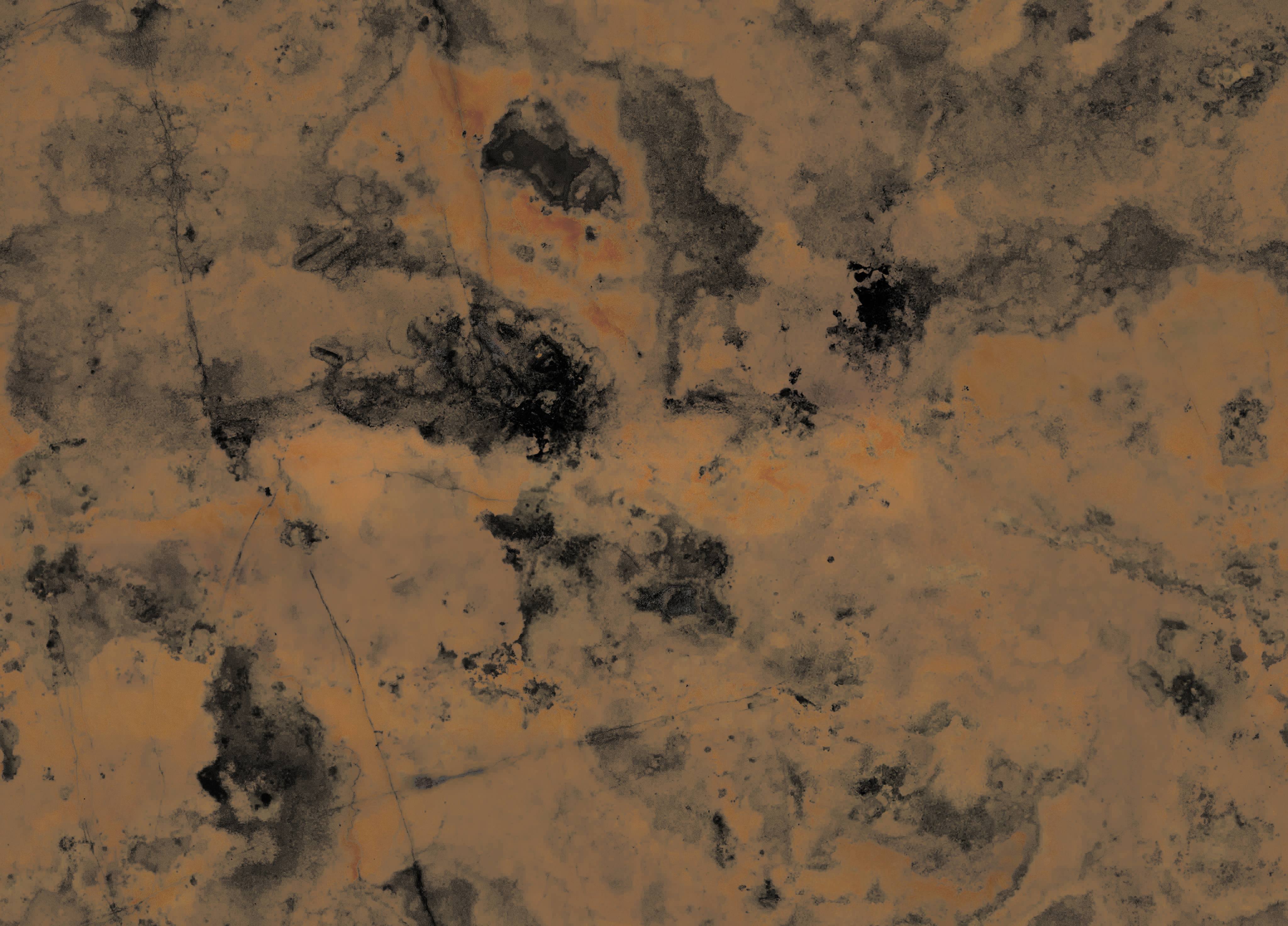
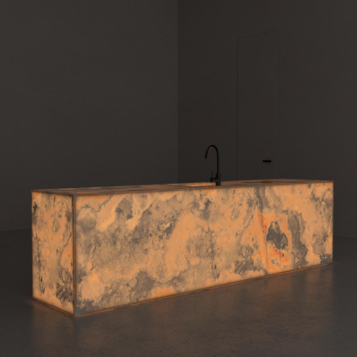
The Translucency map describes how much light passes through a material and becomes visible from the opposite side, especially when the object is backlit. It is useful for thin or semi-thin materials such as leaves, petals, paper, wax, fabric, skin layers, lampshades, thin plastics and organic surfaces where light does not simply reflect from the front surface. Unlike opacity, which primarily controls visibility, translucency controls light transport through the material and helps reproduce the soft glowing effect seen when light penetrates and diffuses through a surface. In modern PBR systems, translucency and transmission are often treated separately from simple alpha transparency because they need to account for absorption, wavelength, thickness and viewing angle in a more physically plausible way.
Subsurface scattering map (SSS)
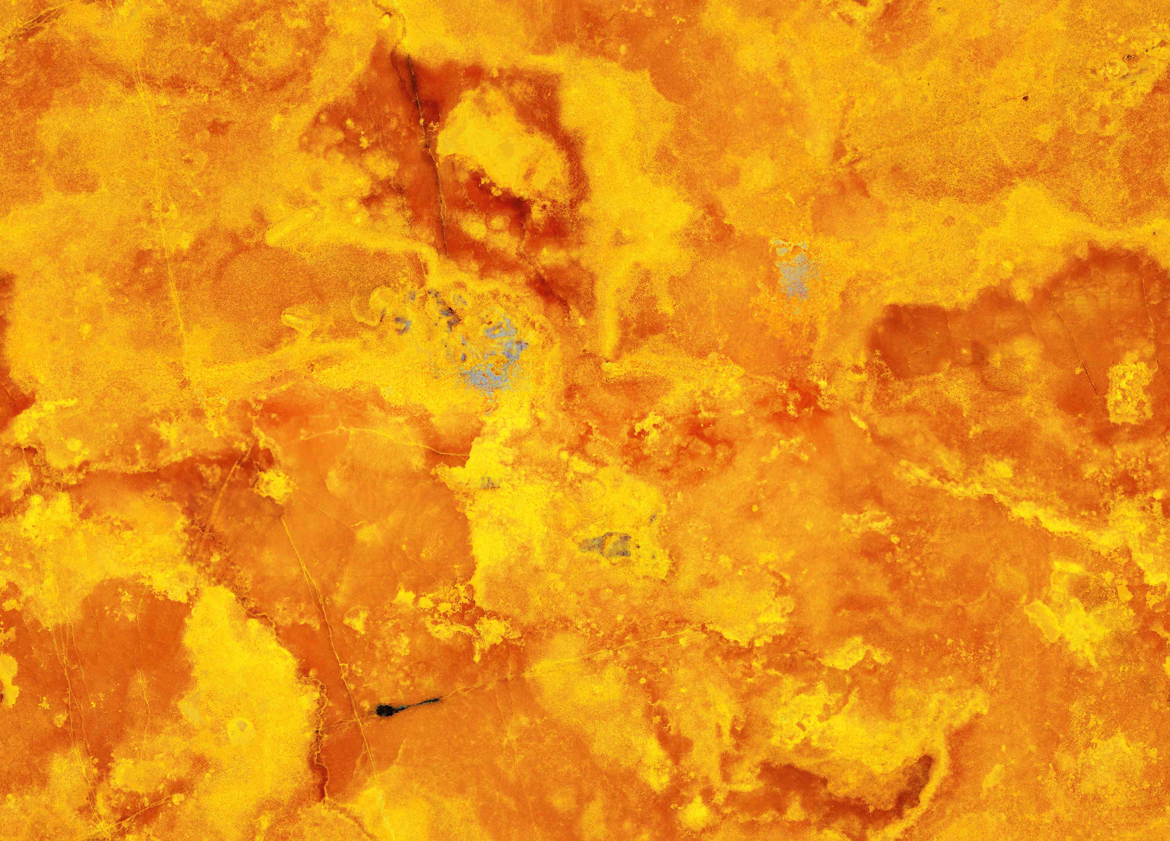
The Subsurface Scattering map controls where light enters a material, scatters beneath the surface and exits nearby, creating a soft internal glow rather than a purely surface-level reflection. This is critical for skin, wax, marble, jade, milk, food, leaves, rubber, silicone, organic tissue and other materials where part of the light penetrates the surface before returning to the camera. A grayscale SSS map usually defines the strength or mask of the effect, while color and radius parameters determine how deeply and in what tint the light scatters. Used correctly, subsurface scattering prevents translucent materials from looking like simple transparent plastic and adds the soft, diffused appearance associated with organic and volumetric surfaces. It should be balanced carefully with roughness, translucency, thickness and albedo to avoid an over-lit or waxy result.
SSS Absorb map
The SSS Absorb map describes how light is absorbed as it travels through or beneath a semi-translucent material. It is closely related to subsurface scattering, translucency and thickness, but instead of only defining where scattering occurs, it helps control how much light is lost inside the material and often what color remains after absorption. This is important for materials such as skin, wax, marble, leaves, fruit, liquids, resin, jade, silicone or organic tissue, where light penetrates the surface and changes color before exiting. A stronger absorption value can make the material feel denser, deeper or more saturated, while weaker absorption allows more light to pass through. SSS Absorb is a linear data map and should be balanced carefully with albedo, SSS strength, radius, translucency and thickness settings.
Sheen map
The Sheen map defines a soft secondary reflection layer that appears most strongly at grazing angles and is especially important for cloth, velvet, suede, felt, microfiber, peach fuzz and other materials with fine fibers. In PBR shading, sheen is commonly layered over the base material to simulate the way tiny fibers scatter light back toward the viewer, creating a subtle rim-like or velvet-like highlight that cannot be reproduced accurately with roughness alone. A sheen texture can control the color and intensity of this effect across the surface, while a sheen roughness channel determines how broad or tight the fabric highlight appears. It is particularly valuable for scanned textiles, upholstery, apparel, carpets and decorative fabrics where the surface response changes dramatically with viewing angle.
Sheen Gloss map
The Sheen Gloss map controls the sharpness of the sheen reflection layer, most commonly used for cloth, velvet, suede, felt, microfiber and other fiber-based materials. While the Sheen map defines the strength or color of the soft grazing-angle reflection, Sheen Gloss determines how tight, polished or broad that secondary highlight appears. Higher gloss values produce a more concentrated, silky or satin-like sheen, while lower values create a wider, softer and more diffuse fabric response. This map is especially useful for scanned textiles and upholstery, where fiber direction, wear and weave density can cause subtle but important variation in the surface highlight. Sheen Gloss is a technical data map and should be interpreted as linear.
Anisotropy map
The Anisotropy map controls directionally dependent reflections, where the highlight stretches or behaves differently along one surface direction than another. This is essential for materials with oriented microstructure, such as brushed metal, satin, hair, carbon fiber, vinyl, machined surfaces or fabrics with visible grain. Unlike standard roughness, which scatters reflections evenly in all directions, anisotropy creates elongated highlights that follow the material’s fiber, brush or scratch direction. In advanced shaders, anisotropy often works together with a tangent, rotation or direction map, because the effect depends not only on strength but also on orientation. ANISO is a linear data map and should be interpreted without color correction.
Additional texture maps may be included in more advanced material workflows, such as Emission, Position, IOR, Thickness, Curvature or various custom mask maps. These maps can provide highly specialized control over light emission, refraction, procedural effects, spatial variation or complex shader behavior. However, they usually go beyond the standard requirements of most everyday users and are mainly intended for high-end visualization, advanced material authoring, real-time engine development or custom production pipelines.
Summary
In simple terms, PBR materials help architects make better visual decisions and help manufacturers bring their real products into the digital design process. They connect the physical sample, the digital model, the visualization, and the final specification.
When materials are accurately scanned, processed, and published through a platform such as Reawote, they become more than technical files. They become a bridge between product brands and the professionals who choose how those products appear in future buildings, interiors, products, and visual experiences.
✍️ What to remember?
📌 PBR is a general standard for describing the visual appearance of materials in 3D software.
📌 PBR materials can be used across modern 3D applications, renderers, and real-time engines.
📌 PBR materials usually need just standard maps described in the section above.
📌 Advanced PBR maps, such as SSS or Sheen, are sometimes necessary for certain surfaces.
Join our community and stay updated on all things 3D
Sign up to our newsletter.


Build a better world with real-world 3D detail
Step into the digital world and explore new ways to create, present, and distribute products — without limits or physical constraints.